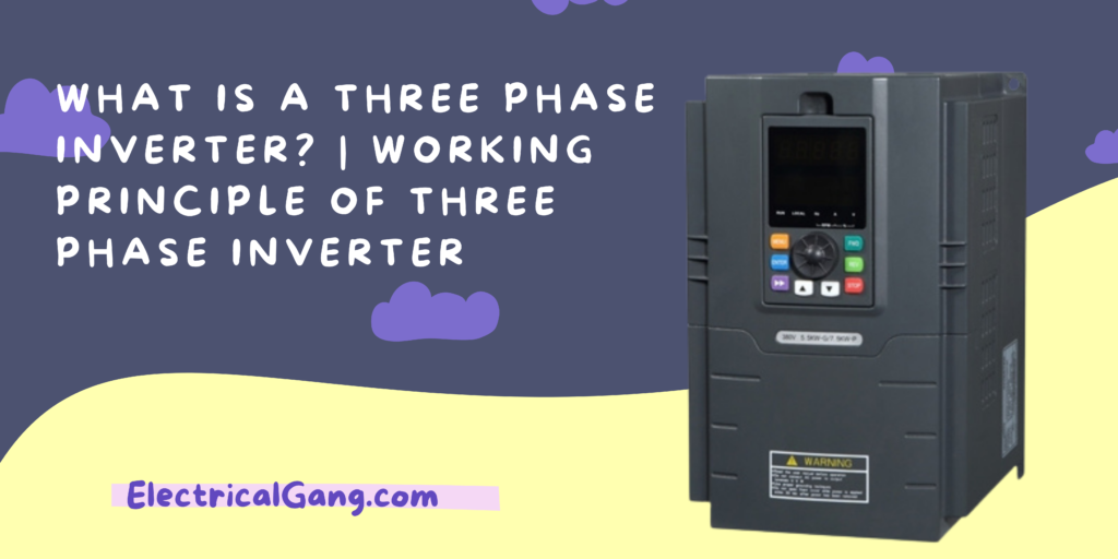
A common inverter is used in our home use and this is found in most of the rural areas as compared to the city area. An inverter is an electrical electronic device. This inverter is used to convert power from one form to another such as DC to AC at the required frequency and voltage output. This can be classified based on the source of supply in the power circuit as well as the related topology.
That is why it is classified into two types VSI (Voltage Source Inverter) and CSI (Current Source Inverter). Inverters of VSI type have an inverter input terminal DC voltage source with low impedance. The CSI-type inverter has DC current source with high impedance. In today’s article, we will see what a 3-phase inverter is. What is the working principle of this inverter and what is a glimpse of the application we talked about today.
What is Three Phase Inverter?

We all know that the function of an inverter is to convert DC current to AC current. We have discussed two types of inverters above. A three-phase inverter is used to convert DC voltage to a three-phase AC supply. This inverter is commonly used in high-power and variable-frequency drive applications such as HVDC power transmission.
Electricity is transmitted across the network with the help of three different currents in a three-phase inverter. Which are out of phase with each other. When in a single-phase inverter the power can go through one phase. For example, if our house has a connection to a three-phase power supply in our house then this can be connected to any one phase.
Working Principle of Three Phase Inverter:
The working principle of this inverter is that it consists of three inverter switches with a single phase. In which each switch can be connected to the load terminal. Three switches can be synchronized to the operation of the basic control system. So that a switch works to create a line / to-line output waveform, including six steps, at every 60 degrees of the basic output waveform.
This wave involves a zero voltage stage between two sections like the positive and negative of a square wave. Once the carrier-based PWM technology is applied to this wave. The original shape of the wave can then be taken. So that the third harmonic including its multiplication will be canceled.
Also Read: What is 2 Way Switch | 2 Way Switch Wiring
Single Phase Inverter:
There are two types of single-phase inverters, one is the full-bridge type and the other is the half-bridge type.
A full-bridge type inverter circuit is mainly used to convert DC to AC. This can be achieved by opening and closing the switch in the correct order. This type of inverter consists of four different operating states where these switches operate on closed switches.
A half-bridge type inverter circuit is the basic building block in a full-bridge type inverter. This inverter consists of two switches. Each type of switch has a capacitor with an output voltage. In addition, these switches complement each other as if the first switch is turned on then the rest of the switch is turned off.
Three-Phase Inverter Design/Circuit Diagram:
 The diagram of the three-phase inverter is as follows. The main function of this type of inverter is to convert the input of DC current to the output of three-phase AC. A basic three-phase inverter consists of three single-phase inverter switches. Jay Each switch can be connected simultaneously from three load terminals.
Normally the three arms of this inverter will be delayed from a 120-degree angle to create a 3-phase AC supply.
The ratio of the switch used in the inverter is 50% and switching can be done after every 60-degree angle. Switches like S1, S2, S3, S4, S5, S6 will complement each other. Thus the three inverters with a single fuse are placed in the same DC source. The poling voltage inside a three-phase inverter is equal to the pole voltage inside a half-phase inverter with a single phase.
The two types of inverters like single-phase and three-phase include two modes of conduction mode 180 degrees and 120-degree conduction mode.
180° Conduction Mode:
In this conduction mode, each device is carried at 180°. Where they are activated at intervals of 60. Outputs like A, B, and C are connected to the three-phase delta connection of the star or load.
 The three-phase balanced load is illustrated in the figure above. For 0 to 60 degrees, switches like S 1, S 5, and S 6 are in Conduction mode. Load terminals like A and C are connected to the source at its positive points. While terminal B is associated with the source at its negative point.
In addition, R/2 resistance is available between the neutral and positive two ends while R resistance is available between neutral and negative terminals.
The voltage of the load in this mode is shown below.
VAN = V/3,
VBN = −2V/3,
VCN = V/3
The line voltage is given below
VAB = VAN − VBN = V,
VBC = VBN − VCN = −V,
VCA = VCN − VAN = 0
Suggested Read: What is a Single Phase Transformer | Construction of Single Phase Transformer
120° Conduction Mode:
In this type of Conduction mode, each electronic device will be in a 120 ° conductor position. It is suitable for delta connection within the load. As it results in a waveform type of 6 steps in one phase. So at any given time, only this device will operate every device that will only operate at 120.
The A terminal on the load can be connected by a positive point. While the B terminal can be connected to the negative terminal of the source. The C terminal on the load that will be in the conductor is known as the floating state. In addition, the voltage of the phase is equal to the voltage of the load which is given below
The phase voltage is equal to the line voltage, therefore
VAB = V
VBC = −V/2
VCA = −V/2
Application of Three-Phase Inverter:
Following are some applications of Three Phase Inverter
- Used in high-power applications such as HVDC power transmission.
- This inverter is used in variable frequency drive applications.
Most Commonly Asked Questions:

What does a 3-phase inverter do?
The three-phase inverter converts DC input to three-phase AC output. His three arms are usually delayed by a 120 angle. So let’s make a three-phase AC supply. Each of the inverter switches is 50%. and switching occurs after every T/6 of the time T 60 ° angle interval.
What are the different types of three-phase inverters?
Based on the inverter output characteristic it is divided into three types which are as follows:
- Sine Wave Inverter.
- Square Wave Inverter.
- Modified Sine Wave Inverter.
What is a three-phase bridge inverter?
A three-phase bridge inverter is a device that converts DC power input to three-phase AC power. Just like a single-phase inverter it also takes DC supply from the battery or more commonly through a rectifier.
What is the difference between single-phase and three-phase inverters?
A Single-phase inverter can be connected and exported to electricity by single-phase power. If you have a 3-phase connection to your home, the inverter will only connect to one of those phases. A three-phase inverter, however, connects all three phases and exports equally.
Like this post? Could you share it with your friends?
Suggested Read –