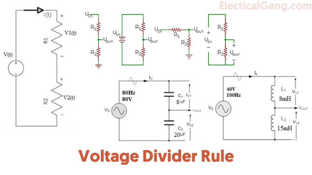
The Voltage Divider rule is the simplest and most important electronic circuit in any electronic circuit. This circuit is used to convert large voltages to small voltages. In this circuit, we can measure the output voltage using only one input voltage and two series resistors. Thus the output voltage is a fraction of the input voltage. The best example of a Voltage divider is when two resistors are connected in series.
When the input voltage is applied to a pair of resistors, the output voltage will appear in the connection between them. This divider is usually used to reduce the intensity of the voltage or create a reference voltage and is used as a signal attenuator at low frequencies. Voltage dividers may be suitable for low frequencies in DC and proportions. If only made up of resistors. Where frequency feedback in a wide range is essential.
In today’s article, we will see what is the Voltage Divider Rule. Today we will talk about Waltage Divider Calculation and its application.
Suggested Read: Types of Losses in a Transformer | Efficiency of Transformer
What is the Voltage Divider Rule?
A voltage divider is a basic circuit in the field of electronics. Which is used to produce part of its input voltage as output. Two resistors are used in the construction of such a circuit. Otherwise voltage source with any passive components.
The resistors in the circuit are connected in series while the voltage source is connected to this resistor. This circuit is also known as a potential divider. The input voltage can be transmitted between two resistors in the circuit so that the voltage is split.
When to use the Voltage Divider Rule?
The law of voltage divider is used to solve the circuit to simplify the solution. Even simple circuits can be completely solved by using this rule. The main concept of this law is that the voltage is divided between the resistors that are connected in series in direct proportion to their resistance. The two important parts involved in a Waltge divider are the circuit and the equation.
Suggested Read: What Is a Tullu Pump? | Types of Tullu Pump
Different Voltage Divider Schematics:
A voltage source is inserted into a series of two resistors in a voltage divider. You can see the different voltage circuits in different ways which are shown below. But these circuits’ different circuits should always be the same.
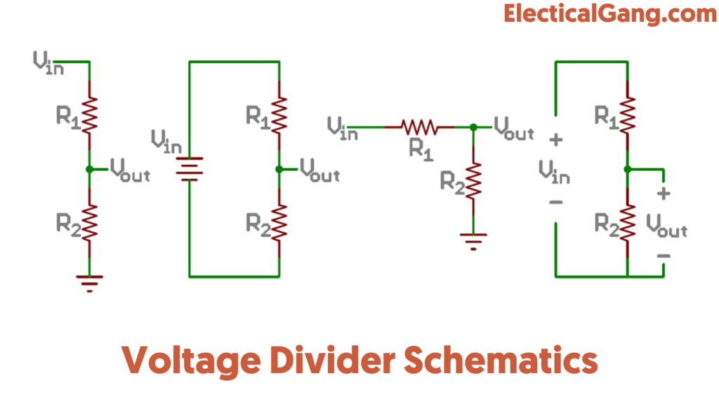
The R 1 resistor input in the various voltage divider circuits shown above is close to the voltage Vin. And resistor R 2 is close to the ground terminal. The voltage drop across resistor R2 is called the watt which is the split voltage of the circuit.
Voltage Divider Calculation:
Let us assume that one of the following circuits is connected to each other using two resistors R1 and R2. Where the variable resistor is connected to the voltage source. In the circuit shown below, R1 is the resistance between the variable sliding contact and the negative terminal. R2 is the resistance between the positive terminal and the sliding contact. This means that R1 and R2 are two resistors connected in series.

According to Ohm’s law V = IR.
From the above equation, we can get the following equation.
V1 (t) =R1i (t)…………… (I)
V2 (t) =R2i (t)…………… (II)
According to Kirchhoff’s Voltage rule
KVL states that when the algebraic sum of the voltage around the closed path in the circuit is equal to zero.
–V (t) +v1 (t) +v2 (t) =0
V (t) = V1 (t) +v2 (t)
Therefore
V (t) =R1i (t)+ R2i (t)= i(t)(R1+R2)
Hence
i (t) =v (t) /R1+R2……………. (III)
Substituting III in I and II equations
V1 (t) = R1 (v (t) /R1+R2)
V (t) (R1/R1+R2)
V2 (t) = R2 (v (t) /R1+R2)
V (t) (R2/R1+R2)
The circuit above shows a voltage divider between the two resistors which is directly proportional to their resistance. This voltage divider can be extended into the rule circuit. Which is designed with more than two resistors.

Rule of voltage division for the above two resistor circuits.
V1(t)= V(t) R1/R1+R2+R3+R4
V2(t)= V(t) R2/R1+R2+R3+R4
V3(t)= V(t) R3/R1+R2+R3+R4
V4(t)= V(t) R4/R1+R2+R3+R4
Suggested Read: What Is an Electrical Resistor? | Types of Resistors | Resistors Color Code Calculation
Voltage Divider Equation:
When you know the three values of the circuit above, the voltage divider that accepts the equation is the input voltage and two resistor values. Using the equation given below, we can find the output voltage.
Vout = Vin. R2 / R1 + R2
The above equation shows that the ratio of Vout (O / P voltage) is directly proportional to Vin (input voltage) and two resistors R1 and R2.
Resistive Voltage Divider:
This circuit is very easy to design and understand. Passive voltage is the basic type of divider circuit that can be made with the help of two resistors connected in series. This circuit uses the law of the Voltage divider to measure the voltage drop across each series resistor. The resistive voltage divider circuit is shown below.
In a resistive divider circuit, both R1 and R2 have connected in the resistor A series. So the current flow in this resistor will be the same so, it provides voltage drop (I * R) in each resistor.

The voltage supply is applied to this circuit using a voltage source. In this circuit, we can measure the voltage drop across the resistor by applying the law of KVL and ohm. Can therefore be given as the flow of current in the circuit.
By applying KVL
VS = VR1 + VR2
According to Ohm’s Law
VR1 = I x R1
VR2 = I x R2
VS = I x R1 + I x R2 = I( R1+R2)
I = VS/ R1+R2
The current flowing through a series circuit is I = V / R according to Ohm’s law. That is why the current flow is the same in both resistances. So now the voltage drop across the R2 resistor in the circuit can be calculated.
IR2 = VR2/R2
Vs/( R1+R2)
VR2 = Vs (R2/ R1+R2)
Similarly, the voltage drop across the R1 resistor can be calculated as
IR1 = VR1/R1
Vs/( R1+R2)
VR1 = Vs (R1/ R1+R2)
Suggested Read: Copper Earthing Strip | Specifications of Copper Earth Strip
Capacitive Voltage Dividers:
The capacitor in this voltage divider circuit produces a voltage drop. Which are connected in series with the AC supply. This is usually used to reduce the extremely high voltage to provide a low output voltage signal. Currently, this divider is applicable to touchscreen tablets, mobiles, and display devices.
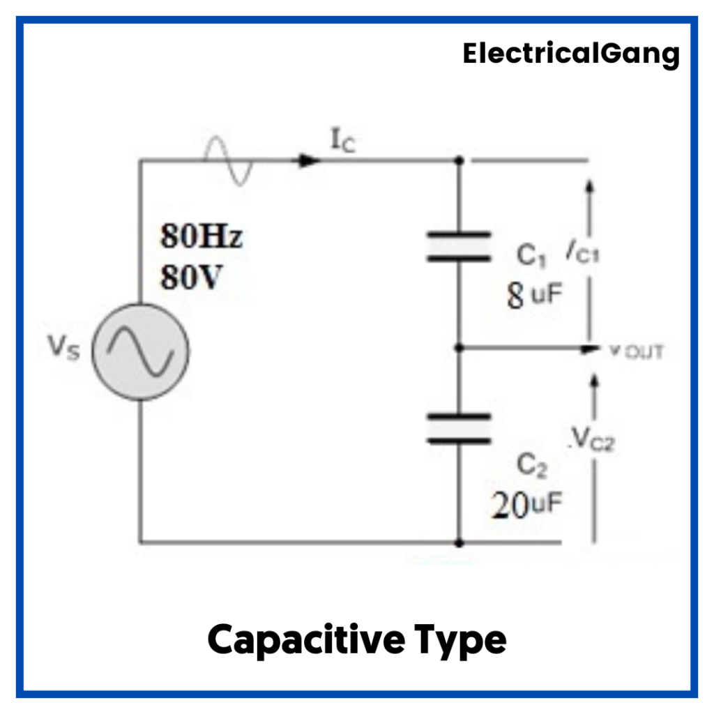
Unlike a resistive voltage circuit, this voltage divider works with a sinusoidal AC supply as the voltage section between the capacitors can be calculated with the help of capacitor reactions. Which depends on the frequency of the AC supply.
Capacitive reactance can be derived as a formula
Xc = 1/ 2πfc
Where:
Xc = Capacitive Reactance (Ω)
π = 3.142 (a numeric constant)
ƒ = Frequency measured in Hertz (Hz)
C = Capacitance measured in Farads (F)
The response of each capacitor can be measured by the voltage as well as the frequency of the AC supply. And you can change it in the above equation to get the same voltage drop in each capacitor.
Using a capacitor connected in series and after connecting to a voltage source we can determine the RMS voltage drop in each capacitor in terms of each response.
Xc1 = 1/ 2πfc1 & Xc2 = 1/ 2πfc2
XCT = XC1 + XC2
VC1 = Vs(XC1/ XCT)
VC2 = Vs(XC2/ XCT)
Capacitive dividers do not allow DC input.
A simple capacitive equation for an AC input is
Vout = (C1/C1+C2).Vin
Suggested Read: Advantages of High Transmission Voltage | Disadvantages of High Transmission Voltage
Inductive Voltage Dividers:
This will create a voltage drop around the coil in the voltage divider. Or the inductor is connected in series with the AC supply. It consists of a coil or a single winding that receives the output voltage from any of the parts. There it is divided into two parts.
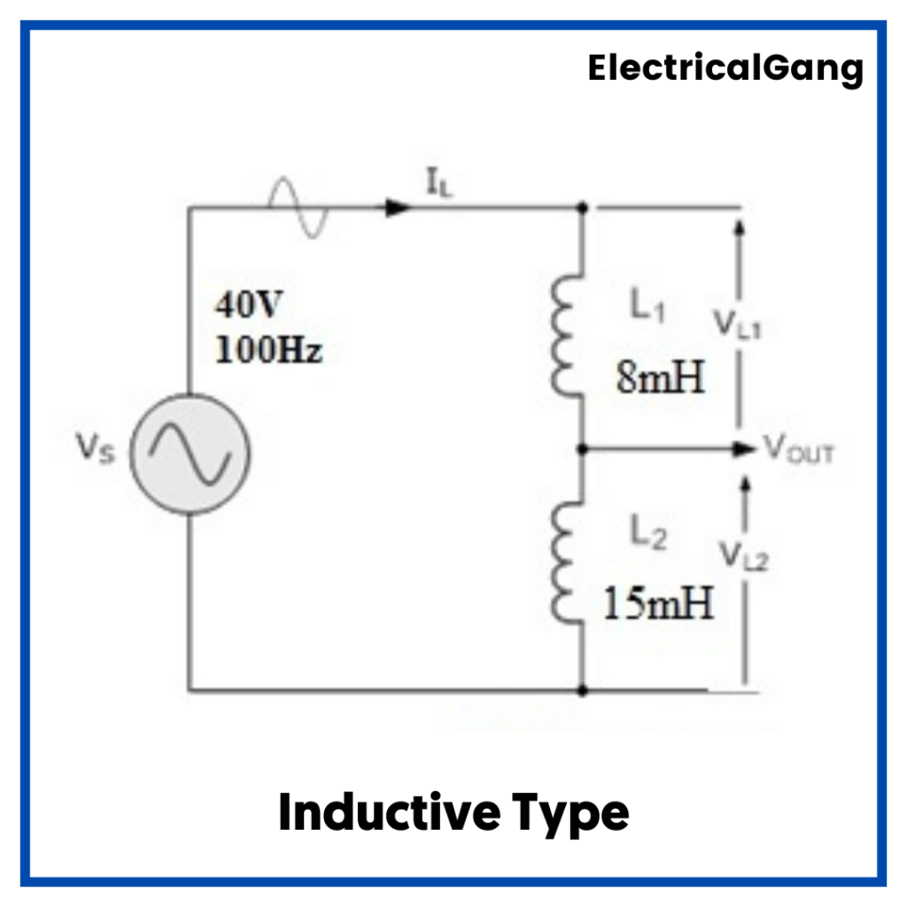
The best example of this Voltage divider is an autotransformer with some tapping points from its secondary winding. A transmitter voltage divider between two inductors can be measured by the reaction of the inductor indicated by XL.
The inductive reactance formula can be derived as
XL = 1/ 2πfL
where:
‘XL’ is an inductive reactance measured in Ohms (Ω)
π = 3.142 (a numeric constant)
‘ƒ’ is the frequency measured in Hertz (Hz)
‘L’ is an inductance measured in Henries (H)
When we get the information on AC supply frequency and voltage, the response of two inductors can be calculated as shown below to get a voltage drop in each inductor to use as per the rule of the Voltage divider.
Using two inductors connected in series in the circuit we can measure the RMS voltage drops in each capacitor in each reactive point after connecting to the voltage source.
XL1 = 2πfL1 & XL2 = 2πfL2
XLT = XL1 + XL2
VL1 = Vs (XL1/ XLT)
VL2 = Vs (XL2/ XLT)
AC input can be split by inductive dividers based on inductance:
Vout = (L2/L1+L2)* Vin
This equation is for inductors that are non-interactive and will change the reciprocal induction results in an autotransformer. DC input can be divided based on the resistance of the elements according to the resistive divider law.
Suggested Read: What is an Ohmmeter? | The Definitive Guide
Voltage Tapping Points in a Divider Network:
When the number of resistors in a circuit is connected in a voltage source vs. series, then the different voltage tapping points can be considered as A, B, C, D, and E.
The total resistance in the circuit can be calculated by adding all the resistance values like 8 + 6 + 3 + 2 = 19 k-ohms. This resistance value will restrict the current flow in the current circuit that produces the voltage supply (VS).
The various equations are used to calculate the voltage drop around a resistor. That is VR1 = VAB,
VR2 = VBC, VR3 = VCD, and VR4 = VDE
The level of voltage at each tapping point is calculated with respect to the GND (0V) terminal. That is why the voltage level at point ‘D’ will be equivalent to VDE, while the level of voltage at point C will be equivalent to VCD + VDE. Here the level of voltage at point C is the ratio of two voltage drops towards two resistors R3 and R4.
So by selecting the set of values of the appropriate resistor, we can create a series of voltage drops. In this voltage drop will be the corresponding voltage value which is obtained only from the voltage. In the example above each output value is positive as the negative terminal (VS) of the voltage supply is connected to the ground terminal.
Applications of Voltage Divider:
Following are some applications of Voltage Divider:
- This voltage divider is used only where a certain voltage is left in the circuit and the voltage is regulated. It is especially used in systems where energy efficiency does not need to be taken seriously.
- Voltage dividers are used to adjust the signal level in the amplifier for voltage measurement and bias of active devices. The multimeter and the Whitestone Bridge include voltage dividers.
- This divider is used to measure sensors, voltage, logic shifting, and signal level adjustment.
- It is used in the case of extremely low frequency and DC
- In general, the resistor divider rule is mainly used to generate a reference voltage or reduce the intensity of the voltage so that the measurement is very simple. In addition; These act as signal attenuators at low frequencies
- Capacitive voltage dividers are used in power transmission to compensate for load capacitance and high voltage measurements.
Most Commonly Asked Questions:

What is the voltage division rule formula?
V (t) (R1/R1+R2) V2 (t) = R2 (v (t) /R1+R2) V (t) (R2/R1+R2) The circuit above shows a voltage divider between the two resistors which is directly proportional to their resistance. This voltage divider can be extended into the rule circuit. Which is designed with more than two resistors.
What are the voltage and current division rules?
A parallel circuit acts as a current divider as the current in the parallel circuit divides into all the branches. And Voltage remains the same as all the current division rule determines the current in the circuit impedance.
What is the voltage drop formula?
The voltage drop of the circuit conductors can be determined by multiplying the current of the circuit by the total resistance of the circuit conductors: VD = I x R.
How do I calculate voltage?
- To find the Voltage, ( V ) [ V = I x R ] V (volts) = I (amps) x R (Ω)
- To find the Current, ( I ) [ I = V ÷ R ] I (amps) = V (volts) ÷ R (Ω)
- To find the Resistance, ( R ) [ R = V ÷ I ] R (Ω) = V (volts) ÷ I (amps)
- To find the Power (P) [ P = V x I ] P (watts) = V (volts) x I (amps)
Like this post? Could you share it with your friends?
Suggested Read –