As we all know, an ammeter is an electronic device used to measure currents; thus, it is connected to a measurement system. In the same way, an ammeter is nothing but an ampere measurement. Ampere is a no unit for measuring a current. This meter is used to measure the current.
There are generally two types of power, one is Alternating current (AC), and the other is Direct current (DC). The Alternating current converts the current into regular intervals while the direct current flows in one direction. In today’s article, we will see what is the working principle of what an ammeter is and about, its types, and much more.
Suggested Read: What is Electric Motor? | Different Types of Electric Motors
What is an Ammeter?
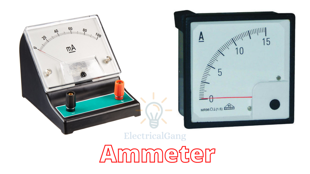
An instrument or device is used to measure the current flowing in an electric circuit. Such an instrument is called an ammeter. The current SI unit is ampere. This is also known as an ammeter or ampere meter as it measures the current. The internal resistance of this device is usually ‘0’, which is also practically correct as it has a small amount of internal resistance. The measurement range of this instrument depends mainly on the resistance value.
The figure of the ammeter is as follows:

Working Principle of Ammeter:
The working principle of an ammeter depends on the current flowing along with its resistance. Very little impedance is used inside the ammeter as it must drop the least amount of voltage attached to it. The ammeter is connected to the series of circuits as the current in the series circuit is the same.
The main function of this tool is to measure the flow of current with the help of a set of coils. Inside this coil, there is very little resistance and inductive reaction.
Suggested Read: What is a Clamp Meter | Construction of Clamp Meter
Types of Ammeters:
The ammeter is classified into six parts based on its application as follows:
| Sr. No. | Types of Ammeters |
| #1 | Moving the coil |
| #2 | Electrodynamic |
| #3 | Moving-iron |
| #4 | Digital Ammeter |
| #5 | Hotwire |
| #6 | Integration |
#1. Moving the coil:
This type of meter is used to measure both AC power and DC power. This device uses magnetic deflection, where the current will flow with the help of a coil to rotate in a magnetic field. The coil in this device rotates freely between the permanent magnet poles.
#2. Electrodynamic:
An electrodynamic ammeter consists of a rotating coil rotating in a field created with the help of a fixed coil. With the help of this instrument, AC and DC power can be measured with an accuracy of 0.1 to 0.25%. This is more reliable when compared to a rotating coil and a fixed coil. The calibration of this device is the same for AC and DC.
#3. Moving-iron:
Moving-iron type ammeters are used to calculate AC power and voltages. This system consists of pieces of soft iron specially made in a movable system, which are acted upon by a fixed coil electromagnetic force made of wire. Devices of this type are classified into two parts, one is repulsion, and the other is attraction.
This device uses different components such as a moving element coil, control, damping, and reflective torque.
#4. Digital Ammeter:
This type of device is used to measure the current in the ampere whose value is displayed on the display. A shunt resistor is included in its design to create a calibrated voltage of such a device, which is in proportion to the current flow.
This device provides information about load and continuity on the current circuit so as to help the customer to overcome variable loads and trends.
#5. Hotwire:
This is used to heat and spread the wire with the help of AC power and DC power, which is known as a hot wire. The working principle of this is that it extends the wire by providing the effect of heat from the current supply. This makes it possible to use both AC and DC flows.
Suggested Read: What is a Hot Wire Instrument?
Ammeter Circuit Diagram Or Ammeter Diagram:
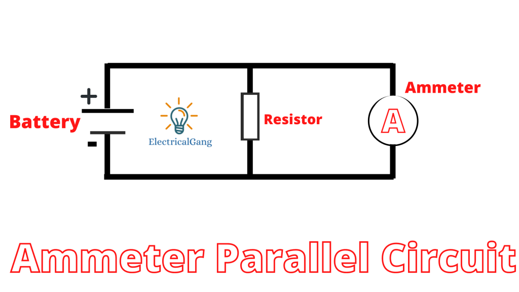
The construction of the ammeter is made possible by both series and shunt. In the figure below, you can see the meter made in both series and shunt, which we will discuss in detail.
First of all, let’s talk about the series.

First of all, let’s talk about the series. Once this meter is connected in series, all the current of the circuit passes through it. So the power consumption is due to its internal resistance and parameter current within this meter. This circuit uses low resistance so that low voltage drops in the circuit.

The resistance is kept low in the parallel ammeter circuit so that the total current will flow from the ammeter and drop low voltage across the device. When a high current from the circuit passes through this device, its internal circuit can be damaged. The shunt resistance is connected in parallel to the emitter to avoid the problem of high currents.
If a high current passes through the circuit, then the main current passes through this shunt resistance. This resistance does not prove to be a hindrance to the function of the device.
Applications of Ammeter:
The uses of the ammeter are as follows:
- The current in a large building is used to measure the current so that the flow is not going more or less.
- This is used to test the functionality of devices in manufacturing and instrumentation companies.
- The application of this device will be from schools to industries.
Most Commonly Asked Questions:
What is the principle of an ammeter and voltmeter?
The voltmeter is connected in parallel to measure its voltages, while the ammeter is connected in series to measure its amperage. In the heart of most analog meters is a galvanometer, an instrument that measures current flow using the movement or bend of a needle.
What are the applications of an ammeter?
The application of the ammeter is as follows:
- The current in a large building is used to measure the current so that the flow is not going more or less.
- This is used to test the functionality of devices in manufacturing and instrumentation companies.
- The application of this device will be from schools to industries.
What are the different types of ammeter?
The ammeter is classified into six parts based on its application as follows:
| Sr. No. | Types of Ammeters |
| #1 | Moving the coil |
| #2 | Electrodynamic |
| #3 | Moving-iron |
| #4 | Digital Ammeter |
| #5 | Hotwire |
| #6 | Integration |
What is the ammeter with a diagram?
This is also known as an ammeter or ampere meter as it measures the current. The internal resistance of this device is usually ‘0’, which is also practically correct as it has a small amount of internal resistance. The measurement range of this instrument depends mainly on the resistance value.
What is the ammeter symbol?
The common symbol for the ampere meter is the capital A specified in a circle. This is how the ammeter symbolizes an electric circuit.
Ammeter Working Principle:
The working principle of an ammeter depends on the current flowing along with its resistance. Very little impedance is used inside the ammeter as it must drop the least amount of voltage attached to it. The ammeter is connected to the series of circuits as the current in the series circuit is the same.
Working of Ammeter:
The resistance of an ammeter is very low. An ammeter is always connected in series with a load to measure its flowing electric current. As such, the ammeter has very low resistance, so when it is connected in series with any circuit, it does not change the current.
Digital Ammeter Working Principle:
The working principle of an ammeter depends on the current flowing along with its resistance. Very little impedance is used inside the ammeter as it must drop the least amount of voltage attached to it. The ammeter is connected to the series of circuits as the current in the series circuit is the same.
AC Ammeter Working Principle:
The working principle of an ammeter depends on the current flowing along with its resistance. Very little impedance is used inside the ammeter as it must drop the least amount of voltage attached to it. The ammeter is connected to the series of circuits as the current in the series circuit is the same.
Like this post? Share it with your friends!
Suggested Read –