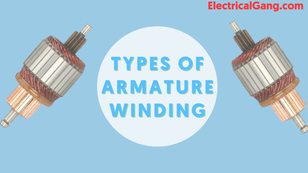
The armature winding is also similar to the stator in which the current passes. The armature windings are covered with a single cotton cover, double cotton cover, or cotton fiberglass and enamel. Typically, rolls of armature windings are interconnected with cotton tape.
The armature coil is soaked in varnish and dried. The armature winding can be defined as a conductor. The armature winding is placed in a properly connected slot which is secured there. The armature winding is arranged neatly in its slot. E.M.F. Will be encouraged which is received across the brush.
In today’s article, we will see what armature winding is and how many types there are. We will discuss this type in detail.
What is Armature Winding?
Armature winding can be expressed in the form of an electric machine. In which EMF is generated due to air gap field flux. One thing to keep in mind here is that the DC current in the winding creates a gap in the air. This winding is usually placed on the field winding on the stator slots and rotor slots.
The figure of DC motor armature winding is as follows.

The field windings on the stator slot and the rotor slot are usually placed on the machine synchronously. The armature winding is placed in the rotor slot while the field winding is placed in the stator slot. Copper is used in the design of armature windings. And this includes a large number of insulated coils. Both these coils have many turns. It can be connected in series or otherwise parallel depending on the type of winding required.
Types of Armature Winding
Different types of alternator armature windings are used. These are as follows
| Sr. No. | Armature Winding Types |
| #1. | Single Phase and Poly Phase Armature Winding |
| #2. | Concentrated Winding and Distributed Winding |
| #3. | Lap, Wave, and Concentric or Spiral Winding |
| #4. | Single Layer and Double Layer Winding |
| #5. | Half Coiled and Whole Coiled Winding |
| #6. | Full Pitched Coil Winding and Fractional Pitched Coil Winding |
Suggested Read: What Is Motor Winding | Types Of Motor Winding | Motor Winding Calculation
#1. Single Phase and Poly Phase Armature Winding
Single-phase armature windings can be either centered or distributed type.
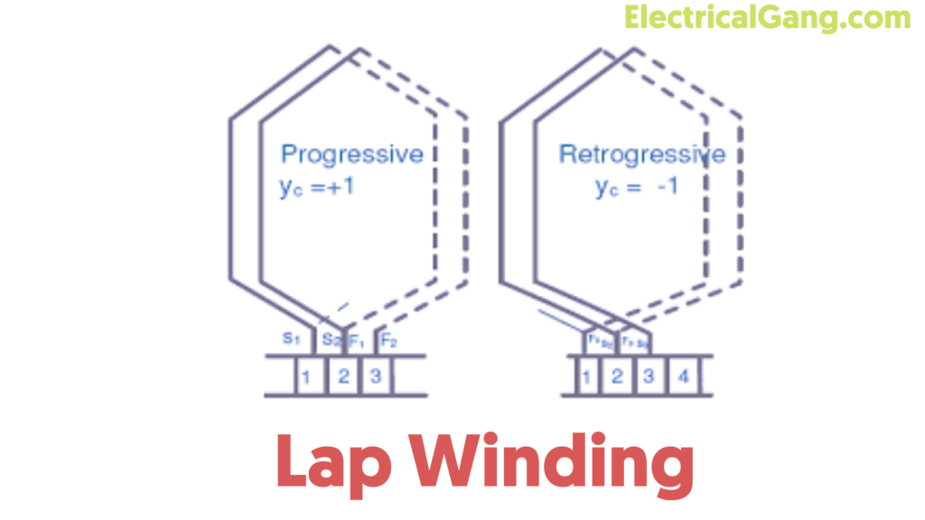
#2. Lap Winding
This type of winding conductor is connected in such a way that its parallel poles and lanes remain the same. The last part of each armature coil can be connected to the adjacent section on the commutator. The number of brushes in this winding can be equal to the number of parallel lanes, and these brushes differ evenly in negative polarity windings as they are positive.
Lap windings are mainly used in machines where high-current, low voltage is required. Lap windings are mainly classified into three sections which are as follows.
- Simplex Type Lap Winding.
- Duplex Type Lap Winding.
- Triplex Type Lap Winding.

#2.1. Simplex Type Lap Winding
In this type of winding, the end of a coil is connected to the commutator and the beginning and end of the secondary coil can be arranged under the same pole. The number of parallel lanes is also equal to the number of pole windings.
#2.2. Duplex Type Lap Winding
In this type of winding, the number of lanes parallel to the pole is the number of poles. Lap windings are used especially in high-current machines. This type of winding is achieved by arranging two identical windings on the same armature as well as by adding the same number of commutator bars towards the primary winding and the number for the secondary winding.
#2.3. Triplex Type Lap Winding
In this type of winding in Triplex Type Lap Winding, the windings are connected to 1/3 g of the bars of the commutator. Such a lap winding consists of many lanes hence it is known as Triplex Type winding. This winding is used especially in wide current applications. The main drawback of this winding is that it uses many conductors which increases the cost of its winding.
Suggested Read: The Best Pole Changing Method | Speed Control for Induction Motor
#3. Wave Winding

This type of winding has only two parallel lanes between the positive and negative brushes. The end of the first armature coil is connected at some distance from the end of the second distance coil commutator segment.
In this type of winding the conductor, and machine pole is connected with two parallel lanes. The number of parallel ports is equal to the number of brushes. This type of winding is applicable for low-current and high-voltage machines.
Once a round is turned the armature winding drops to the left from its starting point. This is why this type of winding is also known as retrograde winding. As such, once the windings of the armature drop to the right on a slot then it is named progressive winding.
Suppose the two winding layers should be on the upper half of the slot to the left or right of the AB conductor. Assume that YF is in the front and YB is in the back. So the amount of this pitch is almost the same as the winding pole pitch. The following equation gives the winding average pitch.
The equation shown provides the standard pitch of the winding.
YA = YB + YF / 2
If the whole number is ZA of the conductor then the normal pitch can be represented according to the following equation.
YA = Z + 2 / p or YA = Z-2 / p
In the above equation, P means Pole and it is always the same. So Z can always be measured with the same digits as Z = PYA ± 2. Here, both symbols + and – are used for progressive winding as well as retrograde windings.
Coil group
It is the number of phases and poles in a rotating machine.
Coil group = Number of Poles × The Number of Phases.
Balanced Winding
If under each pole face, there are coils of an equal number of different phases, then this winding is called balanced winding. In a balanced winding, the coil group should have an equal number.
Suggested Read: Types of Electric Poles in Overhead Transmission Lines
Integral Slot and Fractional Slot Winding
Such windings are known as integer windings when the number of slots per pole per phase is complete. When the number of slots per phase pole is a fraction of the winding. Which we call fractional slot winding.
Fractional slot windings are used only with double-layered windings. It limits the number of parallel circuits available. This is because the phase groups under the many poles must be connected in series before the unit of the unit is formed. And respects the pattern to give the second unit the widening that can be placed parallel to the first.
Like this post? Could you share it with your friends?
Suggested Read –