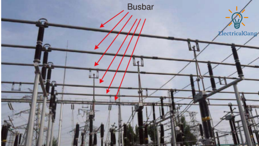
Hello friends, today we will see what is Electrical Busbar what are its types and what are its advantages and disadvantages. In today’s article, we will see.
What is an Electrical Busbar?
An electrical busbar is simply a type of conductor that collects the power supply from the incoming feeder and distributes it to the output feeder as required. In other words, it is a kind of electrical power junction in which all the currents coming and going together meet.
Thus, the electric bus bar collects electric power in one place. Electrical busbars use isolators and circuit breakers that operate at fault times and protect the equipment in the substation.
In the event of a fault, the circuit breaker breaks, and the defective section of the busbar is easily disconnected from the circuit. Busbars are mainly available in rectangular, cross-sectional, round, and many other shapes.
Rectangular bus strips are mostly used in power systems. Copper and aluminum are used for the production of electrical bus bars. The most common size of a busbar is 40×4 mm (160 mm2); 40×5 mm (200 mm2); 50×6 mm (300 mm2); 60×8 mm (480 mm2); 80×8 (640 mm2) and 100×10 mm (1000 mm2).
A variety of busbar configurations are used in the electrical power system. The choice of a busbar depends on various factors such as reliability, flexibility, cost, etc.
It is selected because of the specific qualities mentioned below.
- Its design is simple and does not require much maintenance.
- The maintenance of the system does not affect its continuity.
- Installing a bus bar is cheaper than other systems.
In small substations where there is no constant need for power, a single busbar system is used. However, more than one busbar is used in a large substation as compared to a smaller substation. Due to this, the problem of power trips does not arise.
Suggested Read: Double Cage Rotor of Induction Motor
Types of Electrical Busbars
The types of electrical busbars are as follows
| Sr.No. | Types of Electrical Busbars |
| #1. | Single Bus-Bar Arrangement |
| #2. | Single Bus-Bar Arrangement With Bus Sectionalized |
| #3. | Main and Transfer Bus Arrangement |
| #4. | Double Bus Double Breaker Arrangement |
| #5. | One-and-a-Half Breaker Arrangement |
| #6. | Ring Main Arrangement |
| #7. | Mesh Arrangement |
| #8. | Sectionalized Double Bus Bar Arrangement |
#1. Single Bus-Bar Arrangement
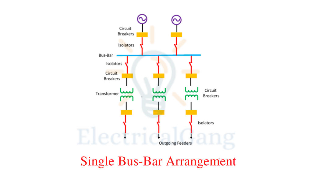
The design of the Single Bus-Bar Arrangement is simple and easy. Only one busbar is connected to the switch system. All substation equipment like a transformer, generator, and feeder is connected only to this bus bar.
Advantages of a single bus bar system
- Its initial cost is low.
- Its maintenance is low.
- It’s easy to operate.
Suggested Read: What Is an Oil Circuit Breaker? | A Complete Guide
#2. Single Bus-Bar Arrangement With Bus Sectionalized

This type of busbar system uses an isolator and a circuit breaker as a switch. The defective part is separated with the help of an isolator. So that the entire power system is protected by a complete shutdown. This system uses more than one circuit breaker which makes a slight difference in the cost of the system.
Advantages of single Bus-bar Arrangement with Bus Sectionalization
- The defective part can be easily disconnected from the system without interrupting the main power supply.
- The defective part can be repaired without breaking the main power supply.
- The current limit reactor is used in this system to reduce the incidence of faults.
Disadvantages of Single Bus-Bar Arrangement with Sectionalization
- Using more than one circuit breaker increases the cost of the system.
#3. Main and Transfer Bus Arrangement
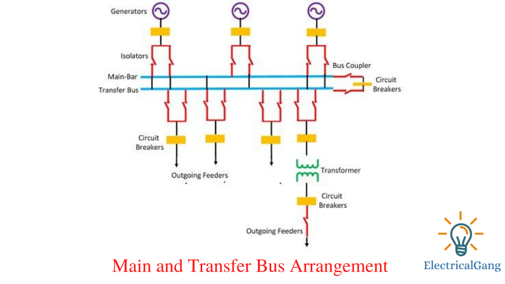
In such a system two busbars are used, the main busbar and the transfer busbar The busbar system uses a bus coupler that connects the different switches that connect the circuit breaker to the busbar. A bus coupler is used to shift the load from one bus bar to another busbar crossing in case of power overload. The following steps can be used to shift the load from one busbar to another busbar
By closing the bus coupler the probability of both bus strips remained the same. The bus strip on which the load is transferred is kept closed. Open the main bus lane.
Advantages of Main and Transfer Bus Arrangement
- Even if there is a fault in the supply system, the power remains on.
- If the primary busbar or the secondary busbar is faulted in either of the two then the whole load shifts from one to the other.
- Repairing can be done without interrupting the power supply.
- The maintenance costs of the system are low.
- It is easy to change the load.
Disadvantages of Main and Transfer Bus Arrangement
- The use of two busbars increases the cost of the system.
- Defects from any of the buses cause a complete shutdown of the entire substation.
Suggested Read: Difference Between AC motor and DC motor
#4. Double Bus Double Breaker Arrangement
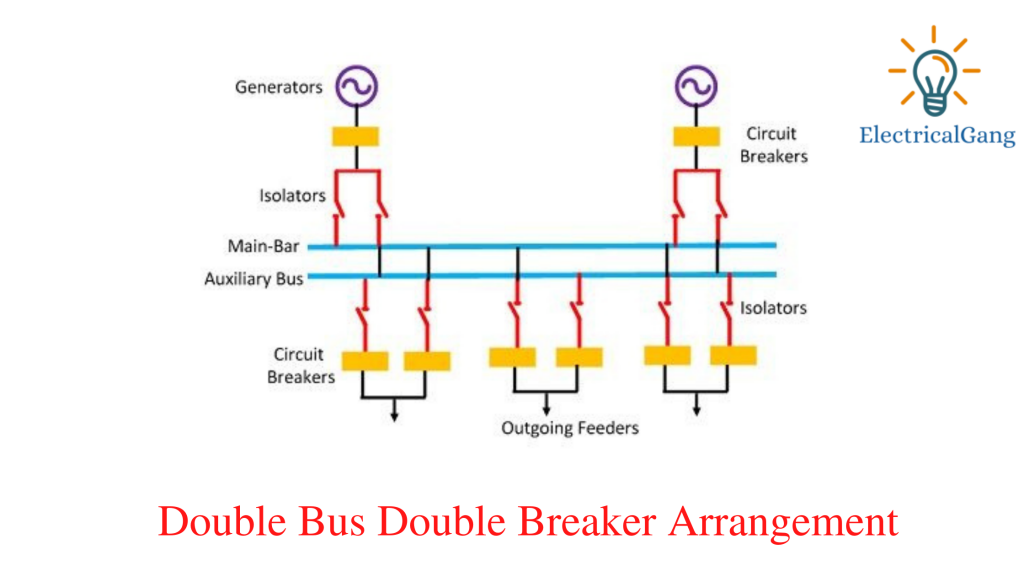
Only 2 bus bar strips and two circuit breakers are used in this system. It does not use a bus coupler and extra switches like the Main and Transfer Bus Arrangement.
Advantages of Double Bus Double Breaker
- This type of configuration provides maximum reliability and flexibility in the supply.
- Because blame and maintenance do not disrupt their continuity.
- The supply meets the constant load and in case of a fault, the load is automatically transferred from one bus lane to another.
Disadvantages of double bus Double breaker
- This system also uses two bus lanes, making the system expensive.
- The maintenance cost of this system is very high.
#5. One-and-a-Half Breaker Arrangement
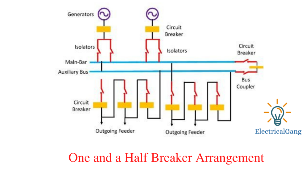
This system uses 3 circuit breakers for 2 circuits. Let each circuit of the bus strip use a circuit breaker. This type of configuration is preferred in large stations where the power handle per circuit is large.
Advantages of One and a Half Breaker Arrangement
- It protects the configuration against supply loss.
- The potential of the bus strip is used to operate the relay.
- In such a configuration, additional circuits are easily added to the system.
Disadvantages of One-a-Half Breaker Arrangement
- The maintenance cost is higher.
- The system becomes complicated as relays are used.
Suggested Read: Difference Between Single Phase and Three Phase AC Power Supply
#6. Ring Main Arrangement

In this system, the starting point of the bus bar and the endpoint are connected together with the help of a ring.
Advantages of Ring Main Arrangement
- Since there are two ways to power supply, the time of fault does not arise during power off.
- The time of fault can be easily separated from the part of the circuit so that the whole circuit is not affected.
- In this configuration, the circuit breaker can be maintained without interrupting the supply.
Disadvantages of Ring Main Arrangement
- There are many difficulties in adding a new circuit.
- Overloading occurs on the system if any of the circuit breakers are opened.
#7. Mesh Arrangement

In this system, the circuit breaker is configured in a net created by Busbar. The circuit is tapped from the node point of the mesh. This type of bus system is controlled by four circuit breakers.
When a defect occurs in any section, two circuit breakers have to be opened, resulting in the mesh opening. This type of arrangement provides protection against bus-bar faults but lacks the switching feature. It is selected for substations with a large number of circuits.
Like this post? Share it with your friends!
Suggested Read –