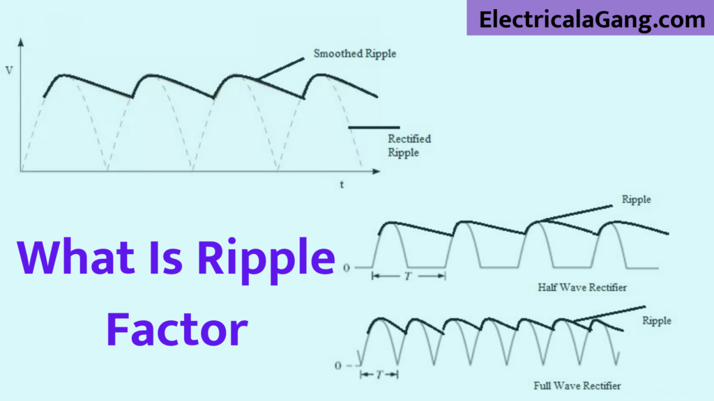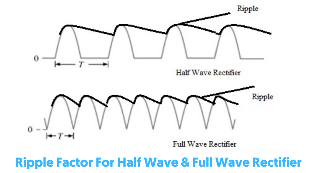
The time when the output power of the rectifier fluctuates is known as a ripple. This factor is, therefore, necessary to measure the rate of fluctuation within the resolved output. This fluctuation can be reduced by using a capacitor or other type of filter.
Capacitors are used in parallel to the thyristor in most circuits like rectifiers. Otherwise, the diode acts as a filter in the circuit. This capacitor helps to reduce the wave inside the output of the rectifier. In today’s article, we will see what the Ripple Factor is and its definition, calculation, its magnitude, and use of RF as are half-wave, full-wave, and bridge corrector.
Suggested Read: What is the Voltage Divider Rule? | Voltage Divider Calculation
What is Ripple Factor?
The output of the rectifier typically consists of the AC component and the DC component. The corrugated can be defined as the AC component within the resolved output. The AC component in the output is against the wall and also gives an estimate of the pulse inside the output of the rectifier. In this, the ripple voltage is nothing but the AC component inside the output of the rectifier. Similarly, the corrugated current output current is an AC component.

The ripple factor can be defined in such a way that the RMS value of the AC component is the ratio of the RMS value of the DC component within the output of the rectifier. Which is denoted by “γ”. And the formula of RF is given below.
(R.F) = AC component’s RMS value / DC component’s RMS value
R.F = I (AC) / I (DC)
This is very important when determining the efficiency of the rectifier’s output. The efficiency of the rectifier can be explained by low RF. The ripple factor of the surplus is nothing but the fluctuations of the surplus AC component which are within the solved output.
By default Ripple’s calculation indicates the clarity of the solve output. That is why not enough effort can be made to reduce RF. Here we are not going to talk about reducing the RF but we are going to talk about why there is a ripple in the output of the rectifier.
Suggested Read: VFD Vs Soft Starter | Difference Between VFD and Soft Starter
Why Ripple Occurs?
Whenever rectification is done by the circuit of the rectifier, there is no possibility of getting DC output. Some variable AC parts often occur at the output of the rectifier. The circuit of the rectifier can be made by a diode. Otherwise, the wave from the thyristor depends mainly on which of the two has been used in its creation.
An example of a single-phase full-wave rectifier is shown below. Four diodes are used in this circuit. So that the output looks like the following waveform.
In this, we have estimated the exact DC output. But due to some ripples inside the output, we cannot get it and it is also known as pulsating AC waveform. We can get almost DC waveform by setting a filter inside the circuit. Which can reduce ripples inside the output.
Derivation of Ripple Factor Formula:
According to the definition of RF, the full load current can be given by the RMS value
IRMS = √I2dc + I2ac
(or)
Iac = √I2rms + I2dc
When the above equation is divided using IDC, then we get the following equation.
Iac / Idc = 1/ Idc √I2rms + I2dc
However, here Iac / Idc is the Ripple Factor Formula
R.F = 1/ Idc √I2rms + I2dc = √ (Irms / Idc)2 -1
Suggested Read: Electrical Substation Components And Their Workings
Ripple Factor of Half Wave Rectifier:
For half-wave rectifiers,
Irms = Im/2
Idc = Im/ π
As we know it R.F = √ (Irms / Idc)2 -1
Substitute the above Irms & Idc in the above equation so we can get the following.
R.F = √ (Im/2 / Im/ π)2 -1 = 1.21
Here, from the above derivation, we have the ripple factor 1.21 of the half-wave corrector. So it is very clear that A.C. The component crosses the DC component inside the half-wave rectifier output. It results in an extra pulse inside the output. That is, this type of rectifier is ineffectively designed to convert AC to DC.

Ripple Factor of Full Wave Rectifier:
For full-wave rectifiers,
Irms = Im/√ 2
Idc = 2Im / π
As we know it R.F = √ (Irms / Idc)2 -1
Substitute the above Irms & Idc in the above equation so we can get the following.
R.F = √ (Im/√ 2/ 2Im / π)2 -1 = 0.48
Here we can know the above derivation that the ripple factor of a full-wave rectifier is 0.48. So this is a very accurate and clear result that in the output of this rectifier, the DC component is higher than the AC component. For this reason, this modification can always be employed when converting AC to DC.
Suggested Read: What Is Motor Winding | Types Of Motor Winding | Motor Winding Calculation
Ripple Factor of Bridge Rectifier:
The factor value of the bridge corrector is 0.482. In fact, the value of RF depends mainly on the wave of the load or the output current. It does not depend on the design of the circuit. So its value will be the same for bridge-like reformers as well as for center-taped when their output waveform is the same.
Ripple Effects:
There are some tools in the market that work easily with Ripple but some sensitive types of devices like audio Dio as well as test supply may not work properly due to the effects of high Ripple. The wave effects of the equipment are mainly due to the following reasons.
- It has a negative effect on the sensitive instrument.
- Ripple effects can cause defects in digital circuits. Data corruption and incorrect output in the logic circuit.
- The Ripple effect can cause heating which can damage the capacitor.
- These effects initiate sound for audio circuits.
Like this post? Share it with your friends!
Suggested Read –
- What is a Signal Isolator? | A Complete Guide
- Highway/Street Light Names And Functions
- How to Fix YouTube TV Freezing Issues in Easy Steps
- How to Solve LG Content Store Not Working Problem?
- What is a Phototransistor | Construction of Phototransistor
- What is a Single Phase Transformer | Construction of Single Phase Transformer
Conclusion:
From the information given above about the ripple factor, we can conclude that a rectifier is usually used to convert an AC signal into an electrical signal. Similarly, there are various types of rectifiers available in the market. Which can be used for improvements like full-wave rectifiers, half-wave rectifiers, and bridge rectifiers.
All of these have specific functionality intended for the applied input AC signal. The corrector factor and efficiency of the rectifier can be measured based on the output.
Very nice explanation, thank you so much 🙏