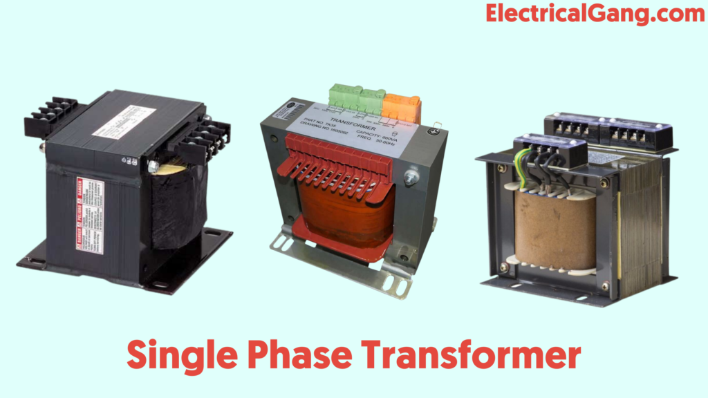
A single-phase transformer is an electrical device. AC power is input and output is also given in single-phase AC. Single-phase transformers are widely used in rural areas. This is because the cost of this transformer is less than that of a three-phase transformer. And the demand for this is even lower than that.
This is used as a step-down transformer to reduce the voltage to the right value for a home without changing the frequency function. For this reason, it is commonly used to power electronic devices in residences. In today’s article, we will see what a single-phase transformer is, why this transformer is constructed and we will talk about its complete overview today.
What is a Single Phase Transformer?

A transformer is a device that converts magnetic energy into electrical energy. This transformer consists of two electrical coils. This winding is known as primary winding and secondary winding respectively. The primary winding in the transformer takes the input power while the secondary winding gives the output power of this transformer.
A magnetic iron circuit called the core is usually used to wrap around this coil. Although these two coils are electrically separate, they are magnetically connected to each other.
When an electric current passes through the primary winding of this transformer it creates a magnetic field. Which induces Voltage in the secondary winding of this transformer. Depending on the application this single-phase transformer is used to step up or step down the voltage at the output. Such a transformer is high efficiency and a low loss power transformer. The diagram of a single-phase transformer is shown above.
Suggested Read: Difference Between Single Phase and Three Phase AC Power Supply
Working Principle of Single Phase Transformer:
The single-phase transformer works on the principle of Faraday’s law of electromagnetic induction. In particular, the mutual induction between the primary winding and the secondary winding is responsible for the operation of the transformer in the electrical transformer.
Single-Phase Transformer Construction:
In a typical single-phase transformer, each winding is cylindrically wrapped around an iron limb to provide an essential magnetic circuit. Which everyone calls “Transformer Core“. Between these two windings provides a path for the flow of a magnetic field to induce a voltage.
The two windings are not close enough to each other for efficient magnetic coupling as shown in the figure. Thus converting and amplifying the magnetic circuit near the coil can increase the magnetic connection between the primary and secondary. Thin steel laminations will be in operation to prevent power loss from the core.
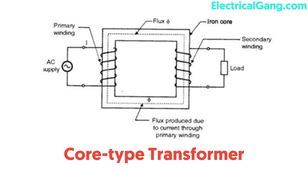
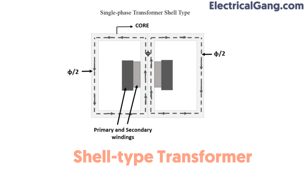
How the winding is wrapped around the central steel laminated core. Based on this, transformer construction is divided into two types. One is a core-type transformer and the other is a shell-type transformer.
Core-type Transformer:
To increase the magnetic attachment in such a transformer, only half the windings are cylindrically wrapped around each leg of the transformer. Whose figure is as follows. This type of construction ensures that the magnetic lines flow simultaneously in both windings. The disadvantage of this type of transformer is the leakage flux caused by the small force flow of the magnetic line outside the core.

Shell-type Transformer:
In this type of transformer, the primary and secondary windings are located cylindrically on the center limb. As a result, the cross-sectional area is twice that of the external organs. In this type of construction, there are two closed magnetic paths, and magnetic flux ɸ / 2 flows in the external limb. This type of transformer eliminates the problem of leakage current. Reduces root damage and increases efficiency.

Suggested Read: What is a Potential Transformer | Construction of Potential Transformer
Working of Single Phase Transformer:
A transformer is a static device that has no moving parts like a motor. Electric power is transferred from one circuit to another with the same frequency in the transformer. This transformer consists of primary and secondary windings. This transformer works on the principle of mutual inductance.
When the transformer is connected to the primary AC supply current flows in the coil and creates a magnetic field. This situation is known as mutual inductance. And the flow of current is according to Faraday’s law of electromagnetic induction. As the current increases from zero to its maximum value. As the magnetic field becomes stronger and dɸ/dt. Is represented by.
This electromagnet creates magnetic lines of force and extends outward from the coil forming a path of magnetic flux. The turns of both windings are connected to this magnetic flux. The strength of the magnetic field generated in the core depends on the number of turns of the winding and the amount of current. The magnetic flux and current are directly proportional to each other.

As the magnetic lines of flux flow around the core. So it passes through the secondary winding and induces a voltage around it. Faraday’s law is used to determine the induced voltage in the secondary coil and is given by:
N. dɸ/dt
Where
‘N’ is the number of coil turns.
The frequency of primary winding and secondary winding is the same.
From this, we can say that Voltage induced is similar in both windings. This is because the same magnetic flux works to connect these two coils together. Also, the total voltage is proportional to the number of direct turns in the induced coil.
Let us assume that the primary winding and the secondary winding of the transformer have a single turn on each. Assuming no loss of any kind, current flows through the coil to generate magnetic flux and induces a voltage of one volt in the secondary winding.
Due to the AC supply, the magnetic flux changes sinusoidally and is given by,
ɸ = ɸmax Sin ωt
The relationship between the induced emf, E in the coil winding of n turns is given by,
E=N (d∅)/dt
E=N*ω*ɸmax cosωtφ
Emax=Nωɸmax
Erms=Nω/√2*ɸmax=2π/√2*f*N*ɸmax
Erms=4.44 fNɸmax
Where,
‘F’ is the frequency in Hz, given by ω / 2π.
‘N’ is the number of coil windings.
‘ɸ’ is the amount of flux in Webers.
The equation shown above is the EMF equation of the transformer. For the EMF of the primary winding of transformer E, N will be the number of primary turns (NP), while for EMF, the number of turns of the secondary winding of the transformer will be N (NS).
Suggested Read: Difference Between Step-up And Step-Down Transformer
Single-Phase Transformer Applications:
Some applications of single-phase transformers are as follows:
- In the television set for voltage regulation.
- To deliver electricity to villages far from urban areas.
- To electrically separate the two circuits, the primary and secondary are kept too far apart.
- Step-up power in the home inverter.
- commercial and residential lighting and heating equipment.
- low voltage electronic devices.
Most Commonly Asked Questions:

Where are single-phase transformers used?
Single-phase transformers are mostly used as electronic devices in commercial low-voltage applications. It acts as a step-down voltage transformer. And reduces the home voltage value to the appropriate value to supply electronics.
What is the working of a single-phase transformer?
A single-phase transformer works to increase or decrease the voltage across the primary winding. When a transformer is used to increase the voltage across the primary winding, it is known as a step-up transformer.
What are the parts of a single-phase transformer?
- an iron core that serves as a magnetic conductor,
- a primary winding or coil of wire and.
- a secondary winding or coil of wire.
What is the transformer “Turns Ratio”?
NP/NS = VP/VS = n = Turns Ratio.
What are the applications of single-phase Transformers?
Some applications of single-phase transformers are as follows:
- In the television set for voltage regulation.
- To deliver electricity to villages far from urban areas.
- To electrically separate the two circuits, the primary and secondary are kept too far apart.
- Step-up power in the home inverter.
Like this post? Share it with your friends!
Suggested Read –
- What is a Signal Isolator? | A Complete Guide
- Highway/Street Light Names And Functions
- How to Fix YouTube TV Freezing Issues in Easy Steps
- How to Solve LG Content Store Not Working Problem?
- What is a Phototransistor | Construction of Phototransistor
- What is a Single Phase Transformer | Construction of Single Phase Transformer