Hello friends, in today’s article we will see what is the potential transformer, why is it constructed and what is the working method of using it. Please read this article in full to know all this. Transformers are electromagnetic inactive devices that work on the principle of electromagnetic induction, which sends electrical energy magnetically from one circuit to another.
This includes two windings, one is the primary winding and the other is. Secondary windings Both windings are magnetically connected without any magnetic core and are found to be electrically separated. The transformer sends electrical energy radiation (voltage/current) from one winding to another winding (coil) by mutual induction.
There is no change in frequency during the conversion of energy. Core-type transformers can be divided into two types one is core type transformers and shell-type transformers. It can also be divided into two parts depending on the voltage, one is the step-up transformer and the other is the step-down transformer.
Depending on the ac circuit also different transformers are used such as power transformers, potential transformers, three-phase transformers, autotransformers, etc.
Suggested Read: Difference Between Capacitor And Battery │Capacitor vs Battery
What is the Potential Transformer?
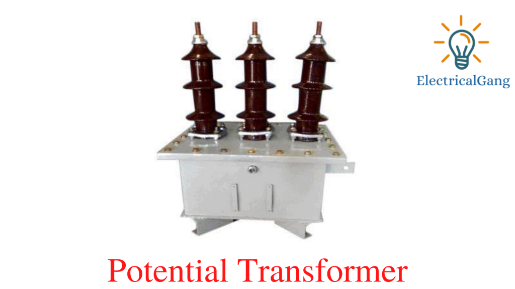
A potential transformer is nothing but a step-down transformer, also known as a voltage transformer or an instrument transformer. In which it is reduced to measure the circuit voltage. The electromagnetic device used to lower the high voltage of a circuit is called a potential transformer.
The output of a low-voltage circuit can be measured by a voltmeter or wattmeter. This can increase or decrease the voltage level of the circuit without changing its frequency and windings.
The working principle of this transformer, construction is similar to other transformers.

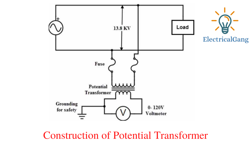
Potential Transformer Circuit Diagram:
Potential Transformer has more turns in the primary winding while secondary windings have fewer turns than primary. High input AC voltage is supplied to the primary winding (or connected to a high voltage circuit for measuring). The low output voltage is taken from the secondary winding using a voltage voltmeter.
The primary winding and the secondary winding are magnetically connected to each other without any connection between the two windings.
Suggested Read: What is a Single Phase Transformer? | A Complete Guide
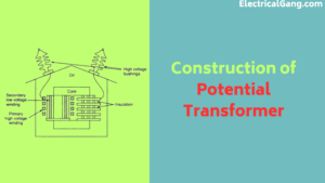
Construction of Potential Transformer:

Potential Transformers are built to maintain high quality to work at low current density, low magnetic flux, and minimum load. When compared to a conventional transformer, it uses larger conductors and an iron core.
It can be easily designed in two forms core type and shell type to ensure the highest accuracy. A potential Transformer is primarily designed to convert from high voltage to low voltage.
These use co-axial windings to reduce the leakage reaction. As we know that Potential Transformer is given high voltage in the primary winding, The high voltage primary winding is divided into smaller parts in turns/coils to reduce insulation costs and losses.
The phase shift between the input voltage and the output voltage should be carefully monitored to maintain a low voltage by isolating the load. To reduce the cost of insulation, windings are covered with vanishing cambric and cotton tape.
Used as a hard fiber divider to separate the coils. Oil-filled bushings are used to connect high-voltage potential transformers (above 7 kV) to the main lines. A multimeter or voltmeter is used to measure the lower output voltage.
Working Method Potential Transformer:
The Potential Transformer with the power circuit whose voltage should be measured is connected between the phase and the ground. This means that the primary winding of a potential transformer is connected to a high voltage and the secondary winding is connected to a voltmeter.
Due to mutual induction, both windings are magnetically connected and operate on the principle of electromagnetic induction. The reduced voltage is measured in the secondary winding concerning the voltage towards the primary winding using a multimeter or voltmeter.
Due to imp impedance in the potential transformer, a small current flows through the secondary winding and acts like a normal transformer with no or low load. So that these types of transformers operate in a voltage range of 50 to 200 VA.
According to the convection transformer, there is a transformation ratio.
V2 = N1/N2
‘V1’ = voltage of the primary winding.
‘V2’ = secondary winding voltage.
‘N1’ = a number of turns in the primary winding.
‘N2’ = a number of turns in the secondary winding.
The high voltage of the circuit can be determined using the above equation.
Suggested Read: Top 10 Best Transformer Company In India
Types of Voltage or Potential Transformers:
Potential Transformers can be divided into two parts based on their function.
1. Metering voltage transformer.
2. Protection voltage transformer.
This transformer is available in both single-phase and three-phase. And is known to work with absolute precision. It is commonly used to operate and control measuring instruments, relays, and other devices.
Electromagnetic Potential Transformers:
This transformer is similar to the primary transformer where the primary and secondary windings are wound on the magnetic core. This transformer operates at a voltage of 130KV or more.
The primary winding is connected to the phase while the secondary winding is connected to the ground. It is used in metering, relays, and high-voltage circuits.
Capacitive Potential Transformers:

This type of transformer is also known as capacitive potential dividers or coupling type or bushing type capacitive potential transformer. The series of capacitors are connected to the primary winding or secondary windings. The output voltage is measured in the secondary winding. It is used for power line carrier communication purposes and is more expensive.
Errors in Potential Transformers:
In the primary transformer, the output voltage in the secondary winding is exactly proportional to the voltage on the secondary transformer. In potential transformers, the voltage decreases due to the reaction and resistance in the primary and secondary And also phase shift errors and voltage errors in the power factor on secondary causes.
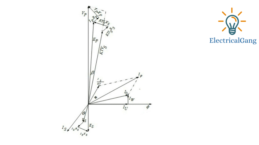
Phase -diagram

The figure above illustrates the faults of potential transformers.
‘Is’ – secondary current.
‘Es’ – induced emf in the secondary winding.
‘Vs’ – terminal voltage of the secondary winding.
‘Rs’ – winding resistance of secondary.
‘Xs’ – winding reactance of secondary.
‘Ip’ – Primary current.
‘Ep’ – induced emf of the primary winding.
‘Vp’ – terminal voltage of the primary winding.
‘Rp’ – winding resistance of the primary winding.
‘Xp’ – winding reactance of primary winding.
‘Kt’ – turns ratio.
‘Io’ – excitation current.
‘Im’ – magnetizing current of Io.
‘Iw’ – core loss component of Io.
‘Φm’ – magnetic flux.
‘Β’- phase angle error.
Induced primary voltage EMF is the subtraction of resistance and reactance drops (IPXP, IPRP) from the voltage of the primary VP.
The voltage drop is due to the experimental reaction and the resistance of the primary winding.
The EMF induced in the primary is converted to secondary by mutual induction and the induced EMF is formed in the secondary AS.
Output voltage vs. secondary winding due to Emf drop by resistance and reaction.
The output voltage on the secondary is obtained by subtracting the reaction and resistance drops (IXX, ISR) from the induced emf in the secondary AS.
Let’s take the mainstream as a reference. Primary IP The current excitation is obtained from the vector sum of the current IO and the reverse secondary current Easter, which is multiplied by 1/kt. VP Is the potential primary voltage applied to the transformer.
Ip = (Io+Is)/Kt
Applications of Potential Transformers:
Some uses of Potential Transformers are as follows:
- Used in relay and metering circuits.
- Used to protect the feeder
- Power line conductors are used in the communication circuit
- Used in the synchronization of generators and feeders.
- Electrically used in defense systems
- Used to protect the barrier in the generator
- Used as protection voltage transformers
Like this post? Could you share it with your friends?
Suggested Read –