The Contactor is an extremely important part of the electrical circuit. Which can be controlled by a given or own power is also a very important part of the starter. It is used to connect and disconnect the power supply operated by the power line and to install and interrupt the electrical power circuit.
This is used to control a complex machine for loading light. It can be considered as the intersection point between the control circuit and the power circuit because it is controlled by the control circuit, it also controls the circuit between power and load.
In today’s article we will talk about the contactor, what is the working principle of why it is constructed, what are its types, and its advantages and disadvantages.
Suggested Read: Electrical Substation Components and Their Workings
What is Contactor?
A contactor is a kind of electrically controlled controlling device. It is used as a switch to turn a machine on and off. The operation of the contactor is similar to that of a relay switch. The difference between the two is that the contactor can carry more load while the relay operates at a lower voltage.
The Contactor cannot provide protection against overload and short circuits but if the voltage of the coil increases it cuts off the main supply.
Construction of a Contactor:

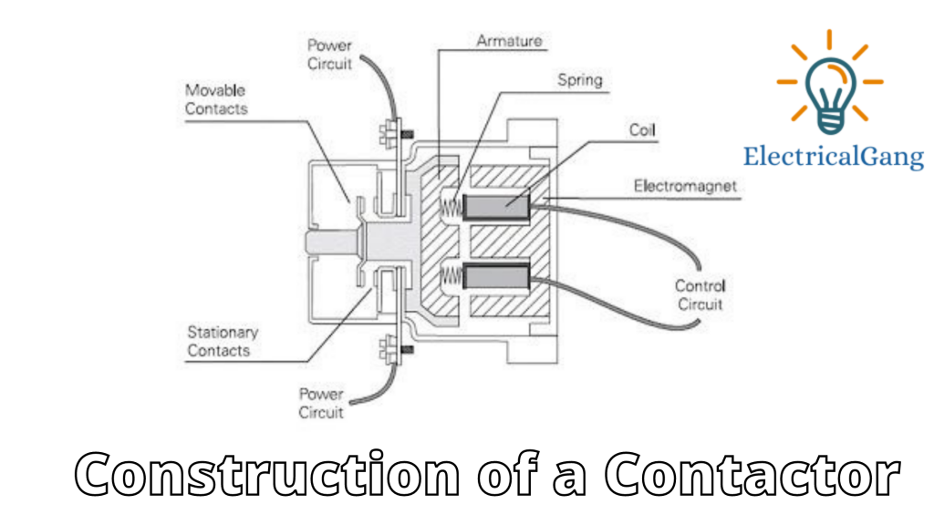
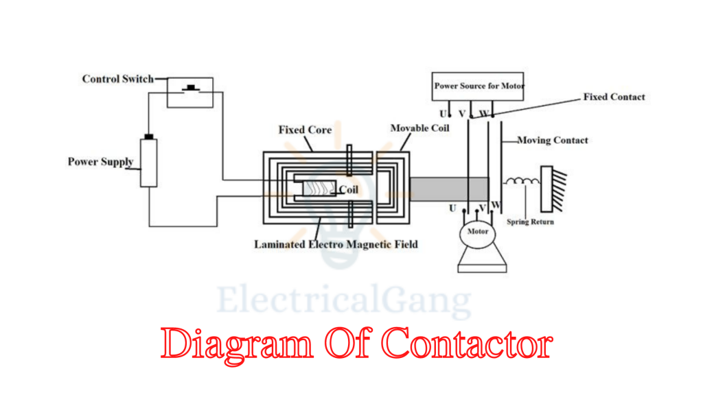
The iron core is used in the contactor. One is a fixed coil while the other is a movable coil and it is an insulated copper coil. The copper coil is attached to the fixed coil. There are 6 terminals for power supply out of which 3 terminals are for fixed coils while the remaining 3 terminals are not for movable coils.
The contactor is made of pure copper whose terminals are specially made to withstand initial and high starting currents and temperatures. A spring is used between the fixed coil and the movable coil which can be opened and closed.
Light current loads such as contact coils, relays, timers, and many other control circuit parts are connected to the main contacts by means of closed and disconnected main contacts.
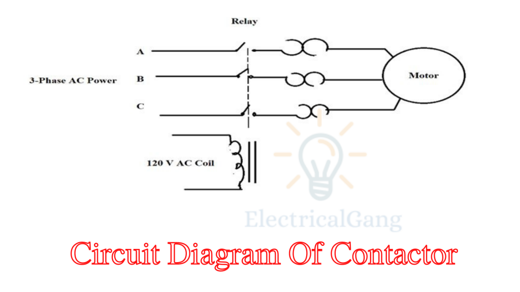
The figure for 3 phase AC power supply is as follows:

The Contactor Has 3 Main Parts:
| Sr. No. | Contactor has 3 Main Parts |
| #1. | Coil |
| #2. | Enclosure |
| #3. | Contacts |
#1. Coil:
The coil gives the force required to close the contactor. This coil is also known as an electromagnet coil. A bond is used to protect the coil and contactor.
#2. Enclosure:
The enclosure acts like an insulator that protects the circuit from any electrical contact, dust, oil, etc. These are made from a variety of materials such as nylon6 thermosetting plastics etc.
#3. Contacts:
Its main function is to carry current in the contactor to different parts of the contactor Such as spring accessory contacts and power contacts etc. Where the part of the contactor has its own function which is explained below by its working principle.
Suggested Read: What is a Potential Transformer | Construction | Working | Types & Its Applications
Working Principle of Contactors:

The time supplied to the contactor generates an electromagnetic field and the fixed coil and the moving coil are attracted to one another. Initially, the current of the electromagnetic field is only more. The moving part pushes the moving coil forward to the side of the fixed coil resulting in the moving part and the fixed part being connected to each other due to the force created by the electromagnetic field.
When the supply to the contactor is stopped, the contactor coil (moving coil) returns to its original position due to the spring or due to the force of gravity. At such times no flow of any kind is carried from the contactor. If the contactor is excited by AC power then a small part of the coil is the shed coil, where the magnetic flux in the core is slightly delayed.
This effect is very average as it prevents the core from humming at twice the line frequency. This process determines whether the contactor works faster or not Internal tipping points are used to do this.
This allows the contactor to be turned on and off quickly. The motor is supplied with power using a contactor in the figure. When the contactor is turned on it is in the switch-off condition and the current flows with the help of the contactor coil and connects the moving coil to the core.
When the moving coil is in contact with the contactor coil As long as the motor remains in running condition. When the power is turned off, the spring of the contactor returns to its original state and the motor stops working.
Suggested Read: Star Delta Starter: Working Principle | Types Of Star Delta Starter | Star Delta Starter Theory
Types of Contactors:
Contactors are selected based on the following factors:
- How many loads it can bear.
- Current capacity.
- The power rating is on this basis.
#1. Knife Blade Switch:
This is the first contactor used to control an electric motor since 1800. Thus the motor is turned on and off using a metal strip.
The disadvantage of this method is that it works very fast and its copper plate gets corroded The size of the motor increases depending on the current capacity which leads to higher physical damage.
#2. Manual Contactor:
The use of a Manual Contactor eliminates some of the disadvantages of the Knife Blade Switch
- The operation performed is absolutely safe.
- They are properly enclosed to protect against external environmental problems.
- The size of the manual connector is small.
- Only one pause is used.
- The switches are controlled using a contactor.
#3. Magnetic Contactor:
The design of this type of contactor is of the most modern type compared to other contactors. It has an electromagnetic type of contactor so it can be turned on and off automatically.
It needs a small amount of control circuit to turn the load on and off. Therefore, the operation of this contactor is safer than that of a manual contactor.
These contactors are widely used in the industrial sector. Since this contactor operates from the electromagnetic type, a very small amount of current is required to make the connection between the load and the power supply.
Suggested Read: What Is an Overload Relay? | Overload Relay Working Principle
Difference between AC Contactors and DC Contactors:
| Sr. No. | AC Contactor | DC Contactor |
| 1 | When the AC contactor shuts down, the fire inside it is automatically extinguished. | It is specifically designed to suppress electrical arching when switching in a DC circuit. |
| 2 | Freewheel diodes are not used | Freewheel diodes are used. |
| 3 | Moving coils have very little time to separate from the fixed coils. | The separation time is increased if the load is heavy and the shunt load is attached to the main contact. |
Advantages of Contactor:
Some of the advantages of contactor are as follows:
- Construction is easy.
- The operation is fast.
- Runs on both AC power and DC power.
Disadvantages of Contactor:
Some of the disadvantages of contactor are as follows:
- In the absence of a magnet-filed, the coil may burn.
- The aging of components causes corrosion of the material when exposed to moisture.
Applications of Contactors:
Applications of Contactors are as Follows:
- Motor Starter.
- It controls the lighting.
- Magnetic starter.
- Vacuum contactor.
- Mercury Relay.
- Mercury-wet relay.
Most Commonly Asked Question:

Why contactor is used?
The contactor is used for high-power applications. They allow low voltages and currents to be switched to a high-power circuit. Therefore they are larger and heavier in size than normal control relays. Which enables them to turn on and off high power loads for thousands of cycles.
How do contactor and relays work?
When a relay is used by its contactor to switch large amounts of electrical power. It is then assigned a special name by the contactor. The contacts usually have a lot of contacts, and those contacts are usually (but not always) open so that the power is turned off for the load when the coil is de-energized.
What are the types of contactor?
The different types of contactors are as follows:
- Auxiliary contact
- Power contact
- Contact spring.
There are also two types of power contactors: static and movable contact. The material for making the contacts should have high welding resistance and static arc resistance.
What is Contactor?
A contactor is a kind of electrically controlled controlling device. It is used as a switch to turn a machine on and off. The operation of the contactor is similar to that of a relay switch.
The difference between the two is that the contactor can carry more load while the relay operates at a lower voltage. The Contactor cannot provide protection against overload and short circuits but if the voltage of the coil increases it cuts off the main supply.
Like this post? Could you share it with your friends?
Suggested Read –
Thanks for the insightful information about power contactors, It means a lot.
Perfect and clear information Thanks!!!
Thank you Nasri Hatibu